


Servos are small motors that can be precisely controlled and often power the movements of small robotic arms. There are many tutorials on how to control them with an Arduino, but fewer tutorials use only a bare AVR chip. In this tutorial, we’ll be using the ATTiny44, a small and cheap microprocessor that also contains a 16-bit timer, which will make our lives a bit easier, as I'll explain later.
Servos can be precisely rotated a specific number of degrees, depending on the pulse width you feed them with the microcontroller. They can also be used as motors to drive a wheel, though you’ll need special ‘continuous rotation’ servos. You’ll often find them in RC cars. So, let's get started and see how you control a servo!
Pulse width modulation
To move the servo, you need to send it a pulse. Depending on the duration of the pulse, the servo positions itself in a fixed position. This position is unique to the pulse duration. In other words, no matter what the current position of the servo is, it always rotates to the same position for a certain pulse duration. The following pulse durations result in the following positions:
- 1ms: 90 degrees to the left
- 1.5ms: Center position
- 2ms: 90 degrees to the right
For most servos, the maximum frequency is around 50 Hz, which means a time period of 20 ms. Of course, the servo is not limited to just 90-degree angles; the angle is proportional to the pulse duration, with a minimum of 0.7 ms and a maximum of 2.3 ms.
Implementing it with an AVR microcontroller
Let's start with the circuit, which is simple.
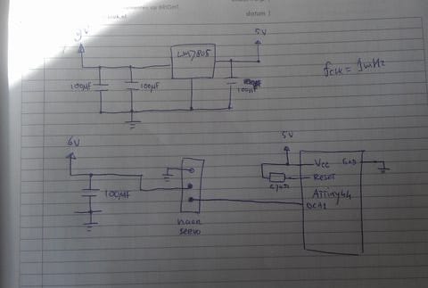
In this case, I use a 9V battery to power my AVR and 4 AA batteries (total of 6V) to power my servo. It’s better to use a different power source for your servos because they can draw high currents when they’re rotating, which could possibly trigger the AVR reset from the resulting voltage drop.
I use the LM7805 to transform the 9V to 5V for the AVR, some capacitors to remove any AC components of the voltage, and a 4.7k resistor as a pull-up for the reset pin.
AVR source code
/* -*- Mode: C; indent-tabs-mode: t; c-basic-offset: 4; tab-width: 4 -*- */
/*
 * main.c - Auto-generated by Anjuta's Makefile project wizard
 *
 */

#ifndef F_CPU
#define F_CPU 1000000L
#endif

#include <avr/io.h>
#include <avr/interrupt.h>
#include <stdint.h>

#define SERVO_PWM_TOP 10000UL // 50 Hz PWM
#define SERVO_LEFT 500UL // Capture value to position the servo to the left (1.0ms)
#define SERVO_CENTER 750UL // Capture value to position the servo in the center (pulse width 1.5ms)
#define SERVO_RIGHT 1000UL // Capture value to turn the servo (pulse width 2ms)

int main(void)
{
	// Setup ports and timers
	DDRA = 0xFF; // All output
	PORTA = 0;

	// Configure timer/counter1 as phase and frequency PWM mode
	TCNT1 = 0;
	TCCR1A = (1 << COM1A1);
	TCCR1B = (1 << WGM13) | (1 << CS10);
	ICR1 = SERVO_PWM_TOP;
	OCR1A = SERVO_LEFT;

	while(1)
	{
	}
}
So, what are we doing here? We will use the AVR's built-in PWM hardware to generate the desired pulse. The ATTiny44 contains a 16-bit timer, which has a special mode called ‘Frequency and phase correct PWM’. Grab the ATTiny44 datasheet and read about it.
To summarize what it does, you provide a TOP value and a compare value. The AVR will then count to the TOP value, and after it has reached that, it counts back to zero. When the counter has the same value as the compare value in OCR1A, something will happen: in the case of up counting, it will reset the pin value of OCA1 to 0, and when down counting, it will set the pin value to 1. This behaviour can be changed by setting the right bits in the TCCR1A/B/C registers. Read the datasheet for more information.
To visualize a bit of what’s happening, here’s a drawing:

Some things you can conclude from the above drawing and description: The value in ICR1 defines the frequency, the value in OCR1A defines the duty cycle.
Calculating the values for ICR1 and OCR1A
So why does the above code has 10000 as value for ICR1, and 500/750/1000 for OCR1A? With a few simple calculations, you can get the values you need:
- Check at which clockfrequency your AVR runs, in our case it’s 1 MHz.
- Because it runs on 1 MHz, if we had an unlimited number of bits for our counter, it would count to 1000000 in one second.
- Almost all servos operate at a frequency of 50 Hz, which means a time period of 20 ms.
- You know this: 1000000 for one second, so 1000000 * (20*10^-3) = 20000 counts for 20 ms.
- In phase and frequency correct mode, it counts up AND down, so we divide the above number by 2, which results in 10000, the value for ICR1. This is why a 16-bit timer is useful: 10000 easily fits in 16 bits and definitely not in 8 bits.
The same can be done to position the servo at the left (a pulse of 1 ms), or at the right (a pulse of 2 ms).
Please note that the above code will constantly pulse every 20 ms. If the servo is already in the right position, it will not move. And it’s probably better to disable the timer, when you’ve sent the pulse. That’s left as an exercise for the reader. ;)
Troubleshooting
- In general, it’s better to use a separate power source for the servos to avoid triggering the AVR's reset. But remember: the grounds of each power source should be connected!
- If you want your servo to rotate continuously, remember to buy one capable of doing that. Most servos can’t rotate a full 360 degrees. However, there are mods to modify a non-continuous rotation servo to one that can rotate the full 360 degrees. You can find a lot of tutorials on Google. And it’s pretty easy.
Thanks for reading, and I hope you enjoyed the article!


